Sharp PC-A820 Specifiche Pagina 15
- Pagina / 33
- Indice
- SEGNALIBRI
- INVERTER 1
- Inverter model 3
- Inverter placement 3
- Installation environment 3
- 2 OUTLINE DIMENSIONS 4
- Terminal connection diagrams 5
- Ó¿·² ½·®½«·¬ 6
- ݱ²¬®±´ ½·®½«·¬ 6
- 3.2 Main circuit terminals 7
- Main circuit terminals 8
- Total wiring length 9
- 3.3 Control circuit terminal 10
- Ú±® -·²µ ´±¹·½ 11
- Ö«³°»® ½±²²»½¬±® 11
- 3.4 Safety stop function 12
- Safety stop function 13
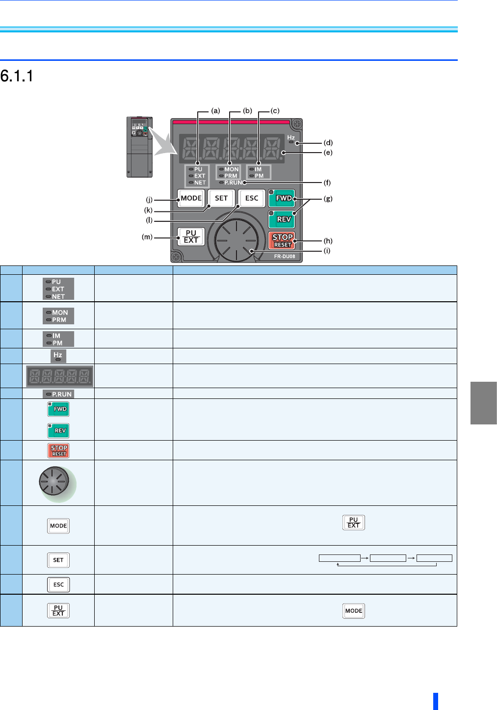
- 6.1 Operation panel (FR-DU08) 15
- DRIVE THE MOTOR 16
- Operation panel (FR-DU08) 16
- 6.2 Parameter list 17
- Parameter list 18
- ײª»®¬»® 23
- 7.2 List of fault displays 24
- 8.1 Rating 25
- 400 V class 26
- EMC Directive 27
- Low Voltage Directive 27
- Wiring protection 28
- Short circuit ratings 28
- Instructions for UL and cUL 29
- Motor overload protection 30
- About the enclosed CD-ROM 31
- First edition 33
- Addition 33
Prodotti e manuali riguardandi Notebook Sharp PC-A820
 (82 pagine)
(68 pagine)
(107 pagine)
(89 pagine)
(93 pagine)
(97 pagine)
(82 pagine)
(68 pagine)
(107 pagine)
(89 pagine)
(93 pagine)
(97 pagine)
 (53 pagine)
(160 pagine)
(48 pagine)
(120 pagine)
(123 pagine)
(46 pagine)
(90 pagine)
(296 pagine)
(97 pagine)
(1 pagine)
(76 pagine)
(53 pagine)
(160 pagine)
(48 pagine)
(120 pagine)
(123 pagine)
(46 pagine)
(90 pagine)
(296 pagine)
(97 pagine)
(1 pagine)
(76 pagine)
© 2020, manymanuals.it. Tutti i diritti riservati | 0.028 s |
 Manymanuals.com
 Manymanuals.de
 Manymanuals.fr
 Manymanuals.it
 Manymanuals.pl
 Manymanuals.cz
 Manymanuals.es
 Manymanuals-pt.com
Commenti su questo manuale