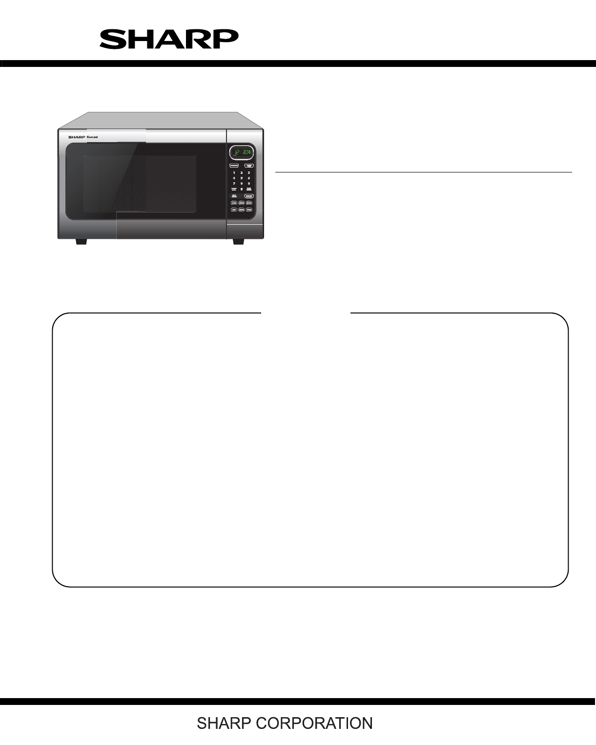
Sharp R-408LS Manuale di Servizio
Navigare online o scaricare Manuale di Servizio per Microonde Sharp R-408LS. Sharp R-408LS Service manual Manuale Utente
- Pagina / 40
- Indice
- RISOLUZIONE PROBLEMI
- SEGNALIBRI
- SERVICE MANUAL 1
- CONTENTS 2
- BEFORE SERVICING 3
- WARNING TO SERVICE PERSONNEL 4
- Don't Touch ! 4
- Danger High Voltage 4
- [1] Requirements: 5
- [2] Preparation for testing: 5
- [3] Leakage test: 5
- FOREWORD AND WARNING 6
- PRODUCT DESCRIPTION 7
- [1] GROUNDING INSTRUCTIONS 8
- [2] OVEN DIAGRAM 8
- 2. TOUCH CONTROL PANEL 9
- CHAPTER 6. OPERATION 10
- [2] OVEN SCHEMATIC 11
- Service Manual 13
- [1] TROUBLESHOOTING CHART 13
- CHAPTER 8. TEST PROCEDURES 14
- [8] G: MONITOR SWITCH TEST 16
- [10] I: NOISE FILTER TEST 17
- [13] L: RELAY TEST 18
- [12] K: KEY UNIT TEST 18
- RY1 and RY2 Relay Test 19
- TOUCH CONTROL PANEL ASSEMBLY 21
- 3. Servicing Tools 22
- 4. Other Precautions 22
- [3] Soldering 23
- WARNING AGAINST HIGH VOLTAGE: 24
- WARNING FOR WIRING 24
- Special screw 25
- Screw Driver 25
- (Type: TORX T20 H or 25
- GTXH20-100) 25
- [6] OVEN LAMP REMOVAL 26
- [8] TURNTABLE MOTOR REMOVAL 26
- [9] COOLING FAN MOTOR REMOVAL 26
- 1. REMOVAL 27
- 2. REINSTALLATION 27
- ADJUSTMENT 28
- [14] DOOR REPLACEMENT 28
- 4. SEALER FILM 29
- CHAPTER 12. CIRCUIT DIAGRAMS 30
- KEY UNIT 31
- PARTS LIST 33
- [1] OVEN PARTS 34
Sommario
PRECAUTIONS TO BE OBSERVED BEFORE ANDDURING SERVICING TO AVOID POSSIBLE EXPO-SURE TO EXCESSIVE MICROWAVE ENERGYBEFORE SERVICINGCHAPTER 1. WARNING TO S
R408LS6 – 1R408LSService Manual CHAPTER 6. OPERATION[1] DESCRIPTION OF OPERATING SEQUENCE The following is a description of component functions during
R408LS6 – 2[2] OVEN SCHEMATIC1. Off Condition Figure O-1. Oven Schematic-
R408LS6 – 3[3] DESCRIPTION AND FUNCTION OF COMPONENTS1. DOOR OPEN MECHANISMThe door is opened by pushing the open button on the control panel,refer to
R408LS7 – 1R408LSService Manual CHAPTER 7. TROUBLESHOOTING GUIDE When troubleshooting the microwave oven, it is helpful to follow the Sequence of Oper
R408LS8 – 1R408LSService Manual CHAPTER 8. TEST PROCEDURES[1] A: MAGNETRON ASSEMBLY TEST1. Disconnect the power supply cord, and then remove outer cas
R408LS8 – 25. Reconnect all leads removed from components during testing.6. Reinstall the outer case (cabinet).7. Reconnect the power supply cord afte
R408LS8 – 3[7] F: SECONDARY INTERLOCK SYSTEM TEST1. DOOR SENSING SWITCH1. Disconnect the power supply cord, and then remove outer case.2. Open the doo
R408LS8 – 4[9] H: BLOWN MONITOR FUSE TEST1. Disconnect the power supply cord, and then remove outer case.2. Open the door and block it open.3. Dischar
R408LS8 – 51) In connection with pads.a) When touching the pads, a certain group of pads do not produce a signal.b) When touching the pads, no pads pr
R408LS8 – 63. Discharge high voltage capacitor.4. Disconnect the leads to the primary of the power transformer.5. Ensure that these leads remain isola
CONTENTSPRECAUTIONS TO BE OBSERVED BEFOREAND DURING SERVICING TO AVOID POSSIBLEEXPOSURE TO EXCESSIVE MICROWAVE ENER-GYBEFORE SERVICINGCHAPTER 1. WARNI
R408LS8 – 75) Make a visual inspection of the varistor. Check for burned damage and examinethe transformer with a tester for the presence of layer sho
R408LS9 – 1R408LSService Manual CHAPTER 9. TOUCH CONTROL PANEL ASSEMBLY[1] OUTLINE OF TOUCH CONTROL PANEL The touch control section consists of the fo
R408LS9 – 22. Servicing the touch control panel with power supply from an exter-nal power source:Disconnect the touch control panel completely from th
R408LS10 – 1R408LSService Manual CHAPTER 10. PRECAUTIONS FOR USING LEAD-FREE SOLDER[1] Employing lead-free solderThe “Main PWB” of this model employs
R408LS11 – 1R408LSService Manual CHAPTER 11. COMPONENT REPLACEMENT AND ADJUSTMENT PROCE-DURE[1] WARNINGSPlease refer to “OVEN PARTS, CABINET PARTS, CO
R408LS11 – 2[2] OUTER CASE REMOVALTo remove the outer case, procedure as follows.1. Disconnect the power supply cord.2. Open the oven door and block i
R408LS11 – 35. Reinstall outer case and check that the oven is operating properly. CAUTION: WHEN REPLACING MAGNETRON, BE SURE THE R.F.GASKET IS IN PLA
R408LS11 – 45. Install the fan motor assembly to the oven cavity back plate withtwo (2) screws. 6. Connect the wire leads to the magnetron and fan mot
R408LS11 – 5[12] DOOR SENSING SWITCH/PRIMARY INTERLOCK SWITCH AND MONITOR SWITCHREMOVAL1. REMOVAL1. Disconnect the power supply cord and remove outer
R408LS11 – 6Figure C-4. Door Disassembly12.Slide latch head upward and remove it from door frame with releas-ing latch spring from door frame and latc
R408LSiR408LSService Manual PRECAUTIONS TO BE OBSERVED BEFORE AND DURING SERVICING TO AVOIDPOSSIBLE EXPOSURE TO EXCESSIVE MICROWAVE ENERGYBEFORE SERVI
R408LS12 – 1R408LSService Manual CHAPTER 12. CIRCUIT DIAGRAMS[1] Pictorial Diagram (Figure S-1)Figure S-1. Pictorial DiagramHIGHVOLTAGECAPACITORH.V. R
R408LS12 – 2[2] Control Panel Circuit (Figure S-2)Figure S-2. Control Panel Circuit LCD (RLCDSA155DR ZZ)R6815KR6915KR7015K15KR7215KR74㨪R78:270Kx5C60㨪C
R408LS12 – 3[3] Printed Wiring Board (Figure S-3)Figure S-3. Printed Wiring Board
PARTS LISTThis document has been published to be usedfor after sales service only.The contents are subject to change without notice.R408LSMICROWAVE OV
R408LS 2[1] OVEN PARTS2-11-64-156-34-134-116-41-104-34-54-76-26-12-27-11-124-107-37-34-11-137-97-57-117-67-87-84-47-101-54-87-71-41-44-67-84-21-91-82-
R408LS3NO. PARTS CODEPRICE RANKNEW MARKPART RANKDESCRIPTION[1] OVEN PARTSELECTRIC PARTS1-1 FPWBFA417WRKZ AY Noise filter assembly1-1 FPWBFA389WRKZ AW
R408LS 4[2] DOOR AND CONTROL PANEL PARTSActual wire harness may be different from illustration.6-66-55-65-75-33-36-73-25-3-15-3-25-25-55-95-95-95-45-8
R408LS5NO. PARTS CODEPRICE RANKNEW MARKPART RANKDESCRIPTION[2] DOOR AND CONTROL PANEL PARTSCONTROL PANEL PARTS3-1 DPNLCC019WRKZ BF Panel med assembly3
R408LS6INDEXPARTS CODE No.PRICE RANKNEW MARKPART RANK[ D ]DPNLCC019WRKZ 2-3-1 BFDPWBFC563WRKZ 2-3-2 BK[ F ]FACCDA083WRE0 1-1-7 AQFACCDA085WREZ 1-1-7
R408LS1 – 1R408LSService Manual CHAPTER 1. WARNING TO SERVICE PERSONNELMicrowave ovens contain circuitry capable of producing very high voltage and cu
EndPageCOPYRIGHT © 2006 BY SHARP CORPORATIONALL RIGHTS RESERVED.No part of this publication may be reproduced, storedin retrieval systems, or transmit
R408LS2 – 1R408LSService Manual CHAPTER 2. MICROWAVE MEASUREMENT PROCEDURE[1] Requirements:1. Microwave leakage limit (Power density limit): The power
R408LS3 – 1R408LSService Manual CHAPTER 3. FOREWORD AND WARNING[1] FOREWORDThis Manual has been prepared to provide Sharp Electronics Corp. Service Pe
R408LS4 – 1R408LSService Manual CHAPTER 4. PRODUCT DESCRIPTION[1] SPECIFICATIONSITEM DESCRIPTIONPower Requirements120 Volts 60 HertzSingle phase, 3 wi
R408LS5 – 1R408LSService Manual CHAPTER 5. GENERAL INFORMATION[1] GROUNDING INSTRUCTIONSThis oven is equipped with a three prong grounding plug. It mu
R408LS5 – 22. TOUCH CONTROL PANELNOTE: Some one-touch cooking features such as “MINUTE PLUS” are disabled after three minutes when the oven is not in
Prodotti e manuali riguardandi Microonde Sharp R-408LS
 (16 pagine)
(21 pagine)
(59 pagine)
(25 pagine)
(2 pagine)
(16 pagine)
(21 pagine)
(59 pagine)
(25 pagine)
(2 pagine)
 (48 pagine)
(31 pagine)
(24 pagine)
(71 pagine)
(42 pagine)
(1 pagine)
(42 pagine)
(55 pagine)
(13 pagine)
(41 pagine)
(2 pagine)
(39 pagine)
(2 pagine)
(40 pagine)
(48 pagine)
(31 pagine)
(24 pagine)
(71 pagine)
(42 pagine)
(1 pagine)
(42 pagine)
(55 pagine)
(13 pagine)
(41 pagine)
(2 pagine)
(39 pagine)
(2 pagine)
(40 pagine)
 (9 pagine)
© 2020, manymanuals.it. Tutti i diritti riservati | 0.076 s |
 Manymanuals.com
 Manymanuals.de
 Manymanuals.fr
 Manymanuals.it
 Manymanuals.pl
 Manymanuals.cz
 Manymanuals.es
 Manymanuals-pt.com
Commenti su questo manuale