A
ll
and more about Sharp PC
-1
500 at http
:/
/www.PC-1500.info
6.
LSI Discription
CDP1854A, COP1854AC Types
1.
Initialization
and Controls
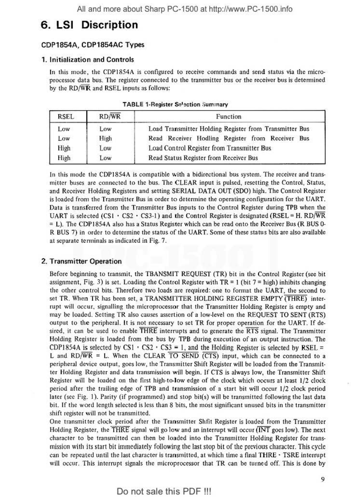
In this mode. the CDPJ854A is configured to recei
ve
commands and send stal\Js
via
t
he
micro-
processor dat.a bus. The register connected
to
the transmitter bus
or
the receiver bus
is
determined
by the RD/WR and RSEL inputs as follows:
TAB
LE
1-Register
Se•,ct
i
on
:;um•nary
RSEL
RD{WR
Function
Low
LO
\V
Load Transmitter Holding Register from Transmitter Bus
LO\\' High Read
Receiv
er Hod
Ung
Register from Receiver Bus
High
Low
Load Control Register from
Tranm
1
iltcr
Hus
High
Low Read
Status
Register from Receiver Bus
In this mode the CDPJ854A is compatible with a bidirectional
bu
s system.
The
receiver and trans·
rnitter buses are connected
to
the bus. The CLEAR
in
put
is
pulsed, resetting
the
Control, Status,
and Receiver Holding Registers
and
setting S.ERIAL DATA OUT(SDO) high. The Control Register
is
loaded
fron
n
th
e
Trans111itter
Bus
in
order
to dete
r1nine
the
oper3ting configuration
for
tlu?
UART
.
Data
is
transferred from the Transmitter Bus inputs
to
the
Control Register
du
ring TPB when the
UART
is
sel
ected
(CS I · CS2 · CS3
·1
) and the Control Register
is
designat
ed
(RSEL
= H. RD/
WR
= L
).
Titc CDPI 854A also has a Status Register wltich can
be
read
onto
the Receiver Bus
(R
BUS
O-
R BUS
7)
in order to determine the status
of
the UART. Some
of
these status bits are also available
at separate te
rm
inals as indi
ca
ted
in Fig. 7.
2. Transmi
tt
er
Operation
Before beginning to traMmit. the TBANSMIT REQUEST
(TR)
bit in the Control Register (see b
it
assignment, Fig.
3)
is
set. Loading the Control Register w
it
h
TR
= I (bit 7 =
ihig)
1) inhibits changing
the
othe
r con trol bits. Therefore two loads arc required: one to format the UART, the second
to
set
TR
.
1~1ien
TR
has been set, a
TR
ANSMITTER HOLDING REGISTER EMPTY (THRE) inte
r-
rupt will occur. signalling the micropr<icessor that the Transmitter
Ho
lding Register
is
empty
and
may be loaded.
S
ett
ing
TR
also causes asscrhon of a low
-l
evel
on
the REQUEST TO SENT
(R
TS)
output
to
the
peripheral.
It
is not necessary to set
TR
for proper operation for the UART.
If
de-
sired, it can
be
used to enable
THRE
intcrr
~1pts
and to generate the RTS s]gnaL The Transmitter
Holding Regist
er
is
loaded from the bus
by
TPB during exe
cutio
n
of
an
output
in
st
ru
ct
i
on
. The
CDPI
854A is selected
by
CS!
•
CS2
•
CS3
-
I,
and
the
Holding Regis
ter
is
se
lected
by
RSEL =
L
and
RD/WR =
L.
When the CLEAR
TO
SEND (CTS) input, which
can
be connected
to
a
peripheral device
output
, goes low, the Transmitter Shift Register
will
be
load
ed from the Transmi
t·
ter
Ho
lding Register and data transmissi
on
will
begin.
If
CTS
is
always low, the Transm
itte
r Shift
Register wi
ll
be
lo
ad
ed
on
t.he
first high-to.l
ow
edge
of
the clock which occurs at least 1/2 clock
period after
'the trailing edge
of
TPll
and
transmi
s.•
i
on
of
a start b
it
will occur 1/2 clock period
later (see
Fig_
I). Parity (
if
programmed)
and
stop bit(s) will be transmitted fo
ll
owing
the
last data
bit.
If
the
word
len
gUt
selected
is
Jess than 8 bits, the most signifi
ca
nt unused bits in the transmitter
shift register w
ill
not
be
transmitted.
One tran
smitte
r clock per
io
d after the Trnnsmitter Shilt Regist
er
is
loaded from the Transmitter
Holding Regi
ster
, the THRE signal
will
go
l
ow
and an interr
upt
will
occur
(INT
goes low). The next
character to
be
transmitted can t.hen
be
loaded
into
the Transmilter Holding Register for trans-
mission
with
its
start
bi!
immediale
ly
following
the
lasl
stop
bit
of t
he
previous
character.
This
cycle
can
be
repea
ted
until the l
as!
character
is
transmitted,
at
which time a final
THRE
· TSRE
intern
1
pt
will occur.
T11is
in
terrupt signals the microprocessor that
TR
can
be
turned
off. This is done by
9
Do
not sale this P
DF!!!


 (89 pagine)


 (210 pagine)
 (11 pagine)
 (14 pagine)
 (15 pagine)


 (28 pagine)
 Manymanuals.com
 Manymanuals.de
 Manymanuals.fr
 Manymanuals.it
 Manymanuals.pl
 Manymanuals.cz
 Manymanuals.es
 Manymanuals-pt.com
Commenti su questo manuale