Sharp SJ-380N Manuale di Servizio Pagina 27
- Pagina / 33
- Indice
- SEGNALIBRI
- SERVICE MANUAL 1
- Refrigerator-freezer 1
- CHAPTER 1. SPECIFICATION 2
- Service Manual 3
- SJ-A31S/A34S 3
- DESIGNATION OFVARIOUS PARTS 4
- [2] CONSTRUCTIONS 5
- CHAPTER 3. DIMENTIONS 6
- (Unit:mm) 7
- [2] INNER DIMENTIONS 8
- 4. SJ-A31S 10
- 5. SJ-A34S 10
- LIST OF ELECTRICAL PARTS 11
- SJD26LVSL 12
- WIRING DIAGRAM 12
- F-LOUVER ASS’Y 13
- 3. Soldering 14
- 1. Employing lead-free solder 14
- CHAPTER 6. FAILURE DIAGNOSIS 15
- Varistor 16
- [5] CONVERSION TABLE 17
- CHAPTER 7. FUNCTIONS 19
- Freezer Temp. Control Knob 20
- 1. Fan motor ass'y 21
- 2. EV-cover ass'y 22
- 3. F - louver ass'y 23
- Figure A-4 24
- Figure A-2 24
- Figure A-3 24
- Detail of D 24
- WIRE COLOR IS GRAY/ORANGE 24
- Fuse ass’y 25
- L-band c 25
- Glass cloth tape 25
- Figure A-5 25
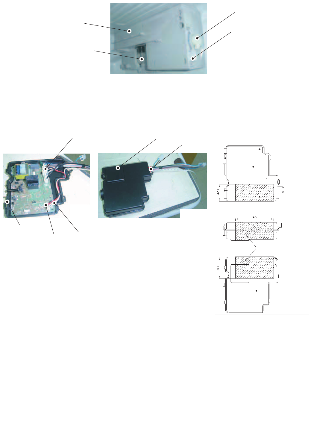
- [3] R CONTROL COV. ASS'Y 27
- Figure A-12 28
- Figure A-13 28
- Control label 28
- R-Control knob 28
- [4] HOW TO REPLACE THE LAMP 29
- [5] DEFROST HEATER 30
- Heater support 31
- Def. heater ass'y 31
- Heater cover 31
- CHAPTER 9. COOLING UNIT 32
- [2] LOCATION 33
Prodotti e manuali riguardandi no Sharp SJ-380N


 (30 pagine)
(235 pagine)
(40 pagine)
(12 pagine)
(12 pagine)
(230 pagine)
(12 pagine)
(24 pagine)
(13 pagine)
(30 pagine)
(15 pagine)
(36 pagine)
(30 pagine)
(235 pagine)
(40 pagine)
(12 pagine)
(12 pagine)
(230 pagine)
(12 pagine)
(24 pagine)
(13 pagine)
(30 pagine)
(15 pagine)
(36 pagine)

 (89 pagine)

 (210 pagine)
(69 pagine)
(210 pagine)
(69 pagine)
 (11 pagine)
(41 pagine)
(14 pagine)
(7 pagine)
(118 pagine)
(11 pagine)
(41 pagine)
(14 pagine)
(7 pagine)
(118 pagine)
© 2020, manymanuals.it. Tutti i diritti riservati | 0.266 s |
 Manymanuals.com
 Manymanuals.de
 Manymanuals.fr
 Manymanuals.it
 Manymanuals.pl
 Manymanuals.cz
 Manymanuals.es
 Manymanuals-pt.com
Commenti su questo manuale