Sharp AR-CF2 Manuale di Servizio Pagina 34
- Pagina / 42
- Indice
- RISOLUZIONE PROBLEMI
- SEGNALIBRI
- SERVICE MANUAL 1
- [1] PRODUCT OUTLINE 2
- [2] SPECIFICATIONS 2
- 1. External components 3
- 2. Sensors and switches 3
- [4] OPERATIONAL DESCRIPTION 5
- [Paper loading] 6
- [Separation] 6
- [Leading-edge registration] 6
- [Transport] 6
- [Paper exit] 6
- (online) 7
- 4. Offline mode setting 8
- 6. Paper jam/error detection 10
- [5] DISASSEMBLY AND ASSEMBLY 11
- 2. Paper Feed Unit 12
- C. Reverse Roller 13
- D. Paper Guide 13
- 3. Drive Unit 14
- 4. Other Parts 14
- 5. Note on assembly 14
- [6] MAINTENANCE 15
- [7] TROUBLESHOOTING 16
- [8] ELECTRICAL SECTION 18
- 2. Circuit Description 19
- Reverse Sensor 20
- Tray Sensor 22
- (3) Motor Drive Circuits 23
- Registration CL 24
- Flapper SOL 24
- Not Mounted 24
- Operator Panel 25
- (9) Operator Panel Circuit 26
- LEAD-FREE SOLDER 30
- CIRCUIT DIAGRAM 31
- [1] BLOCK DIAGRAM 32
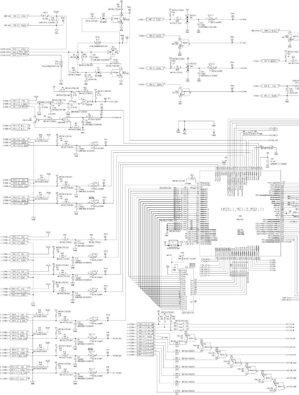
- [2] ACTUAL WIRING CHART 33
- Main Unit +24V 34
- JAM Cover Open/ 34
- Closed SW 34
- Main Unit +5V 34
- Finisher I/F 35
- 2. PARTS LAYOUT 36
- B. SOLDER SURFACE 37
- CAUTION FOR BATTERY DISPOSAL 41
- Trademark acknowledgements 42
Prodotti e manuali riguardandi Fotocopiatrice Sharp AR-CF2
 (200 pagine)
(12 pagine)
(56 pagine)
(208 pagine)
(19 pagine)
(4 pagine)
(68 pagine)
(200 pagine)
(12 pagine)
(56 pagine)
(208 pagine)
(19 pagine)
(4 pagine)
(68 pagine)
 (32 pagine)
(95 pagine)
(31 pagine)
(43 pagine)
(80 pagine)
(82 pagine)
(42 pagine)
(42 pagine)
(149 pagine)
(80 pagine)
(88 pagine)
(56 pagine)
(174 pagine)
(32 pagine)
(95 pagine)
(31 pagine)
(43 pagine)
(80 pagine)
(82 pagine)
(42 pagine)
(42 pagine)
(149 pagine)
(80 pagine)
(88 pagine)
(56 pagine)
(174 pagine)
© 2020, manymanuals.it. Tutti i diritti riservati | 0.037 s |
 Manymanuals.com
 Manymanuals.de
 Manymanuals.fr
 Manymanuals.it
 Manymanuals.pl
 Manymanuals.cz
 Manymanuals.es
 Manymanuals-pt.com
Commenti su questo manuale